7 Essential EMC Tests for Electric Vehicles
An in-depth guide to the seven essential EMC tests required for electric vehicles, covering radiated emissions, conducted emissions, radiated immunity, BCI, ESD, transients, and magnetic field immunity.
Introduction
Electric vehicles present unique electromagnetic compatibility challenges that go far beyond those of conventional internal combustion engine vehicles. High-voltage battery packs operating at 400 V or 800 V, traction inverters switching hundreds of amperes at tens of kilohertz, onboard chargers, DC-DC converters, and battery management systems all generate significant electromagnetic emissions. At the same time, the sophisticated electronic systems that control vehicle dynamics, autonomous driving functions, and infotainment must remain immune to these disturbances.
Regulatory frameworks including UNECE Regulation No. 10 (ECE R10), CISPR 25, and the ISO 11452 series define the tests that electric vehicles and their components must pass. The following seven EMC tests form the core of any EV compliance program.
1. Radiated Emissions
Purpose
Radiated emissions testing ensures that the electromagnetic energy unintentionally radiated by the vehicle or component does not interfere with external communications services, other vehicles, or nearby electronic systems. For EVs, the traction inverter and its cabling are typically the dominant emission sources.
Standard Reference
- Vehicle level: ECE R10 (CISPR 12 methodology), measured with an antenna at 3 m or 10 m distance
- Component level: CISPR 25, measured in a shielded chamber with an antenna at 1 m distance
Test Setup Summary
The vehicle or component is placed in a semi-anechoic chamber or on an open-area test site. A receiving antenna scans the frequency range from 150 kHz to at least 2.5 GHz. The vehicle is operated in a defined driving mode (motor running at specified torque and speed on a dynamometer or with wheel simulation). Peak and average emission levels are compared against the applicable limits.
2. Conducted Emissions
Purpose
Conducted emissions testing measures high-frequency noise currents that travel along the vehicle power supply wiring, charging cables, and signal lines. In EVs, the onboard charger is a critical source of conducted emissions on the AC mains connection, while the DC-DC converter and traction system generate conducted noise on the high-voltage and low-voltage DC buses.
Standard Reference
- Component level: CISPR 25 (150 kHz to 108 MHz on power and signal lines)
- Charger AC mains: CISPR 32 or local grid-connection standards
Test Setup Summary
An artificial network (LISN or AN) is inserted in the power supply line to provide a defined measurement impedance. A spectrum analyzer or EMI receiver measures the noise voltage across the LISN output. For high-voltage DC bus measurements, specialized high-voltage LISNs rated for 1000 V DC or higher are required.
3. Radiated Immunity
Purpose
Radiated immunity testing verifies that the vehicle and its electronic systems continue to function correctly when exposed to external radio-frequency electromagnetic fields. EVs must withstand RF fields from broadcast transmitters, mobile phone base stations, nearby vehicle radar, and handheld radios used inside the cabin.
Standard Reference
- Vehicle level: ECE R10 (ISO 11451-2), tested from 20 MHz to 2 GHz or higher
- Component level: ISO 11452-2 (antenna method in a shielded chamber)
Test Setup Summary
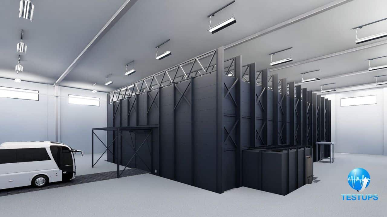
The vehicle is placed in a large semi-anechoic chamber and irradiated by an antenna producing calibrated field strengths from 30 V/m up to 200 V/m depending on the component criticality. The vehicle systems are monitored for malfunctions, resets, warning lights, or degraded performance. For safety-related functions such as braking and steering, no degradation is permitted even at the highest test levels.
4. Conducted Immunity — Bulk Current Injection (BCI)
Purpose
BCI testing injects RF current directly onto the wiring harness of an electronic module to simulate the effect of electromagnetic fields coupling onto vehicle cabling. This method is more repeatable and cost-effective than radiated immunity testing for component-level evaluation and is widely used by automotive OEMs.
Standard Reference
- ISO 11452-4 (BCI method for component testing)
- Typical frequency range: 1 MHz to 400 MHz
Test Setup Summary
A BCI clamp (an RF current transformer) is clamped around the wiring harness of the device under test. A power amplifier drives the clamp to inject a calibrated RF current. The injection level is specified in milliamperes (typically 30 mA to 300 mA depending on the OEM specification) or in terms of forward power. The DUT is monitored for performance degradation during the sweep across the frequency range.
5. Electrostatic Discharge (ESD)
Purpose
ESD testing simulates the discharge of static charge accumulated on a human body to exposed vehicle surfaces and electronic modules. In dry climates, a person exiting a vehicle can accumulate 15 kV or more of static charge. A discharge to an electronic connector, touchscreen, or control panel can cause immediate damage or temporary malfunction.
Standard Reference
- ISO 10605 (automotive-specific ESD)
- Covers both Human Body Model (150 pF / 330 ohm) and an alternative network (330 pF / 2000 ohm)
Test Setup Summary
An ESD generator is applied to all user-accessible surfaces, connector pins, and housings of the electronic module. Both contact discharge and air discharge methods are used at voltage levels from 2 kV up to 25 kV depending on the installation location and OEM requirements. The module must either continue operating normally or recover automatically after each discharge.
6. Transient Immunity
Purpose
The 12 V and high-voltage electrical systems of a vehicle generate severe voltage transients during events such as load dump (alternator disconnection), jump-start, inductive load switching, and superimposed alternating voltage from the alternator. Electronic modules must withstand these transients without damage or malfunction.
Standard Reference
- ISO 7637-2 (transient conducted disturbances along supply lines for 12 V and 24 V systems)
- ISO 16750-2 (electrical loads and environmental conditions, including HV transients)
Test Setup Summary
A transient pulse generator produces standardized waveforms that are coupled onto the power supply lines of the DUT. The key pulse types include:
| Pulse | Description | Typical Peak Voltage |
|---|---|---|
| Pulse 1 | Disconnection of inductive loads by another device | -100 V to -150 V |
| Pulse 2a | Sudden interruption of supply to the DUT (ignition off) | +50 V to +100 V |
| Pulse 2b | Sudden interruption of supply to the DUT (ignition off, inductive) | -200 V to -600 V |
| Pulse 3a/3b | Switching transients from distributed switching | Up to +/-200 V, fast repetitive |
| Pulse 5a | Load dump from alternator disconnection | Up to +120 V (clamped), duration 400 ms |
| Pulse 5b | Load dump for 24 V systems | Up to +202 V |
The DUT is monitored throughout the test for malfunctions, resets, or permanent damage.
7. Magnetic Field Immunity
Purpose
Strong low-frequency magnetic fields are present in EVs due to the high currents flowing through the traction motor, power cables, and battery busbars. These magnetic fields can interfere with sensors (especially Hall-effect current sensors and magnetoresistive devices), navigation compasses, and other sensitive electronics.
Standard Reference
- ISO 11452-8 (magnetic field immunity, component level)
- Typical frequency range: DC to 200 kHz
Test Setup Summary
The DUT is placed inside a Helmholtz coil or similar magnetic field generation system. A defined magnetic field strength (typically up to 1000 A/m for EV-related applications) is applied across the frequency range. The DUT is monitored for measurement errors, communication faults, or functional degradation. This test is particularly critical for battery management system current sensors and ADAS sensor modules.
How TESTUPS Can Help
TESTUPS offers a complete suite of EMC testing services for electric vehicles and their components, covering all seven tests described in this article. Our facilities include large semi-anechoic chambers for vehicle-level radiated testing, high-voltage LISN systems for conducted emissions on EV power trains, high-power BCI and transient test equipment, and calibrated ESD generators for ISO 10605. We support EV manufacturers and tier-one suppliers from early design-stage EMC reviews through final regulatory testing for ECE R10 type approval.
For more details on individual tests, see our articles on ISO 10605 ESD testing, ESD testing fundamentals, and UNECE regulations.
Need Expert EMC Assistance?
TESTUPS provides complete EMC solutions — from test equipment and anechoic chambers to certification services. Contact our team for tailored support.