Power Line EMC Filters — TESTUPS Filter Selection Guide & Datasheets
TESTUPS power line and signal line EMI filter selection guide: TPFXY6 shielded-room series, TPFXY2 EMC-chamber series, full naming-convention key, worked examples, and 50+ downloadable datasheets covering the complete filter range.
🇺🇸 Introduction to Power Line EMC Filters
⚡ Power line EMC filters are passive networks installed at the AC mains input of electronic equipment to suppress conducted electromagnetic interference. Every device that connects to the utility grid can both emit and receive interference through its power cord. Regulatory frameworks such as CISPR 32, EN 55032, and FCC Part 15 set strict limits on conducted emissions in the 150 kHz to 30 MHz band. A properly chosen power line filter attenuates these emissions below the applicable limits while also improving the immunity of the equipment to disturbances arriving on the mains.
Without adequate filtering, switching power supplies, motor drives, LED drivers, and similar products will almost certainly fail conducted emissions testing. The filter is therefore one of the most cost-effective EMC countermeasures available to design engineers.
How Power Line Filters Work
A power line filter exploits the impedance mismatch principle. It places reactive elements (inductors and capacitors) between the noise source and the measurement point so that high-frequency energy is reflected back toward the source or diverted to ground. The filter must handle two distinct noise modes:
- Differential mode (DM): Noise current flows on the line conductor and returns on the neutral conductor. DM noise is generated mainly by the switching action of power converters.
- Common mode (CM): Noise current flows in the same direction on both line and neutral and returns through the ground conductor. CM noise is typically caused by parasitic capacitances between switching nodes and the chassis.
Most commercial EMI filters address both modes simultaneously by combining X-capacitors (line-to-neutral) for DM suppression and Y-capacitors (line-to-ground or neutral-to-ground) with common-mode chokes for CM suppression.
Filter Topologies
Power line filters are classified by the arrangement of their reactive elements. The principal topologies are:
| Topology | Elements | Typical Use | DM | CM |
|---|---|---|---|---|
| C | Single capacitor stage | Minimal filtering, low-cost consumer products | Low | Low |
| LC (L-section) | Inductor + capacitor | General-purpose equipment | Moderate | Moderate |
| Pi (CLC) | Capacitor-inductor-capacitor | High-performance power supplies, medical | High | High |
| T (LCL) | Inductor-capacitor-inductor | Motor drives, industrial inverters | High | High |
| Multi-stage | Two or more cascaded LC sections | EMC test chambers, sensitive instruments | Very high | Very high |
Higher-order topologies deliver steeper roll-off in the stopband but occupy more board or chassis space and add cost. The choice of topology depends on the required insertion loss, available volume, and budget.
Key Selection Criteria
Insertion Loss
Insertion loss is the primary performance metric of an EMI filter. It is specified in decibels (dB) as a function of frequency and is measured separately for common mode and differential mode according to CISPR 17 (EN 55017). When selecting a filter, compare the insertion loss curve against the margin you need at each frequency. A safe design rule is to target at least 10 dB of margin above the required attenuation to account for manufacturing tolerances and installation parasitics.
Rated Current
The filter must carry the full load current of the equipment without excessive temperature rise. Datasheets specify rated current at a given ambient temperature, typically 40 degrees Celsius. Derate the current if the filter will operate in a hotter environment. Undersizing the current rating leads to core saturation in the common-mode choke, which dramatically reduces attenuation at the moment it is needed most.
Rated Voltage
Select a filter rated for the nominal mains voltage plus transient headroom. For worldwide 100-240 VAC applications, a 250 VAC-rated filter is the minimum. Equipment destined for three-phase 480 VAC industrial mains requires filters rated at 520 VAC or higher. Voltage ratings also apply to the X-capacitors and Y-capacitors inside the filter.
Leakage Current
Y-capacitors create a leakage current path from line or neutral to ground. Medical equipment (IEC 60601-1) limits earth leakage to very low values, often below 500 microamperes. In such cases, the Y-capacitor values must be small, which limits CM attenuation. Some manufacturers offer medical-grade filters with reduced Y-capacitor values and enhanced CM chokes to compensate.
Single-Phase vs Three-Phase
Single-phase filters are used in most consumer and light industrial products. Three-phase filters are required for industrial motor drives, large UPS systems, and EV charging stations. A three-phase filter may be configured in a three-line-plus-neutral or three-line-only arrangement, depending on the supply system.
🔧 Installation Best Practices
Even a well-specified filter can underperform if it is installed incorrectly. Observe these guidelines:
- Mount the filter at the point where the power cable enters the enclosure to minimize the length of unfiltered wiring inside the chassis.
- Bond the filter housing directly to the metal enclosure with a low-impedance connection. Paint, anodizing, or powder coating under the mounting surface must be removed.
- Route the filtered output wiring away from the unfiltered input wiring to prevent coupling that bypasses the filter.
- Keep the ground lead between the filter and the chassis as short as possible.
TESTUPS Power Line EMI Filter Selection Guide
The TESTUPS power line EMI filter family is built around two product lines: the TPFXY6 shielded-room series, specified by overall shielding effectiveness, and the TPFXY2 EMC-chamber series, specified by insertion loss. Within each family, four sub-models (A, B, C, D) extend the low-frequency cutoff progressively lower, from 150 kHz down to 10 kHz.
The applications column in the tables below is a simplification — the right model for your facility depends on what is required of the shielded room, cage, or chamber: which tests are being performed, and which standard applies.
🛡️ Shielded-Room Series (TPFXY6)
| Model | Key Performance Indicator | Typical Application |
|---|---|---|
| TPFXY6A-I | Shielding Effectiveness > 100 dB from 150 kHz to 40 GHz | Shielded rooms. TPFXY6C products are also used on antenna chambers where testing begins at higher frequencies. |
| TPFXY6B-I | Shielding Effectiveness > 100 dB from 100 kHz to 40 GHz | Shielded rooms. TPFXY6C products are also used on antenna chambers where testing begins at higher frequencies. |
| TPFXY6C-I | Shielding Effectiveness > 100 dB from 14 kHz to 40 GHz | Shielded rooms. TPFXY6C products are also used on antenna chambers where testing begins at higher frequencies. |
| TPFXY6D-I | Shielding Effectiveness > 100 dB from 10 kHz to 40 GHz | Shielded rooms. TPFXY6C products are also used on antenna chambers where testing begins at higher frequencies. |
EMC Chamber Series (TPFXY2)
| Model | Key Performance Indicator | Typical Application |
|---|---|---|
| TPFXY2A-I | Insertion Loss > 100 dB from 150 kHz to 40 GHz | EMC chambers where strict radiated emission (RE) and/or conducted emission (CE) testing is conducted. |
| TPFXY2B-I | Insertion Loss > 100 dB from 100 kHz to 40 GHz | EMC chambers where strict radiated emission (RE) and/or conducted emission (CE) testing is conducted. |
| TPFXY2C-I | Insertion Loss > 100 dB from 14 kHz to 40 GHz | EMC chambers where strict radiated emission (RE) and/or conducted emission (CE) testing is conducted. |
| TPFXY2D-I | Insertion Loss > 100 dB from 10 kHz to 40 GHz | EMC chambers where strict radiated emission (RE) and/or conducted emission (CE) testing is conducted. |
Naming Convention
Every TESTUPS power line filter model number follows the same six-position scheme:
Position 1 — TPF · Testups Power Filter
Position 2 — X · Number of lines: 1, 2, 3 or 4
Position 3 — Y · Surface finishing technique: 0 = nickel-plated, 6 = brushed surface, 8 = spray coating
Position 4 — 6 or 2 · Application: 6 = shielded rooms / enclosures · 2 = EMC anechoic chambers
Position 5 — A / B / C / D · Low-frequency cutoff at > 100 dB: A from 150 kHz · B from 100 kHz · C from 14 kHz · D from 10 kHz
Position 6 — -I · Current limit per line, in amperes (e.g. -32, -400)
Worked Examples
TPF282C-400
| Code | Meaning |
|---|---|
| TPF | Testups Power Filter |
| 2 | Number of lines |
| 8 | Spray coating |
| 2C | Insertion loss > 100 dB from 14 kHz to 40 GHz — application: EMC chambers for radiated and conducted emissions testing |
| -400 | Current limit is 400 A per line |
TPF462D-32
| Code | Meaning |
|---|---|
| TPF | Testups Power Filter |
| 4 | Number of lines |
| 6 | Brushed surface |
| 2D | Insertion loss > 100 dB from 10 kHz to 40 GHz — application: EMC chambers for radiated and conducted emissions testing |
| -32 | Current limit is 32 A per line |
📥 Download the Selection Guide
The complete TESTUPS Power Line EMI Filter Selection Guide — including the naming convention and the worked-example breakdowns above — is available as a PDF below. Use the button to save a copy for offline reference, RFQs, or design reviews.
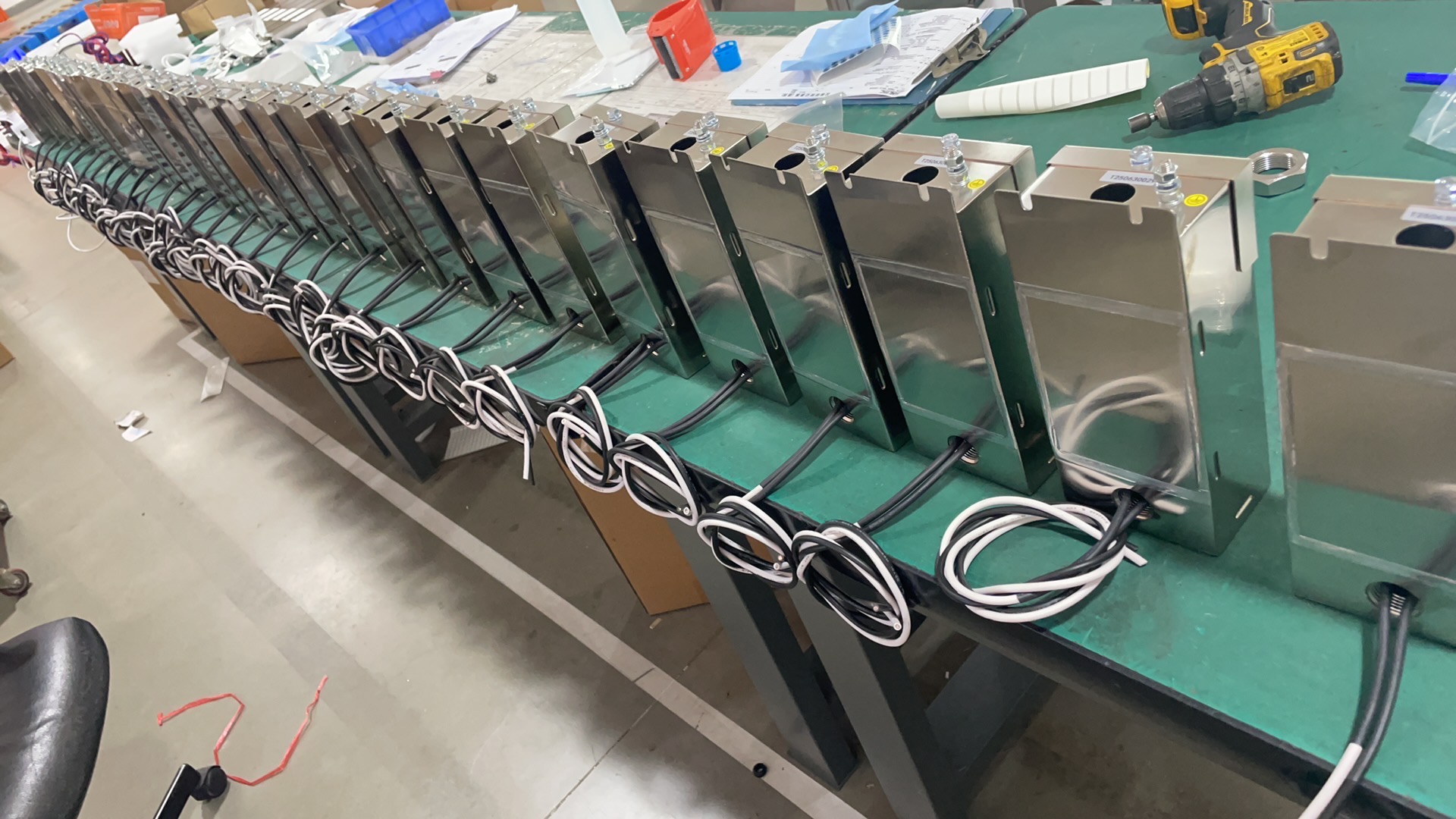
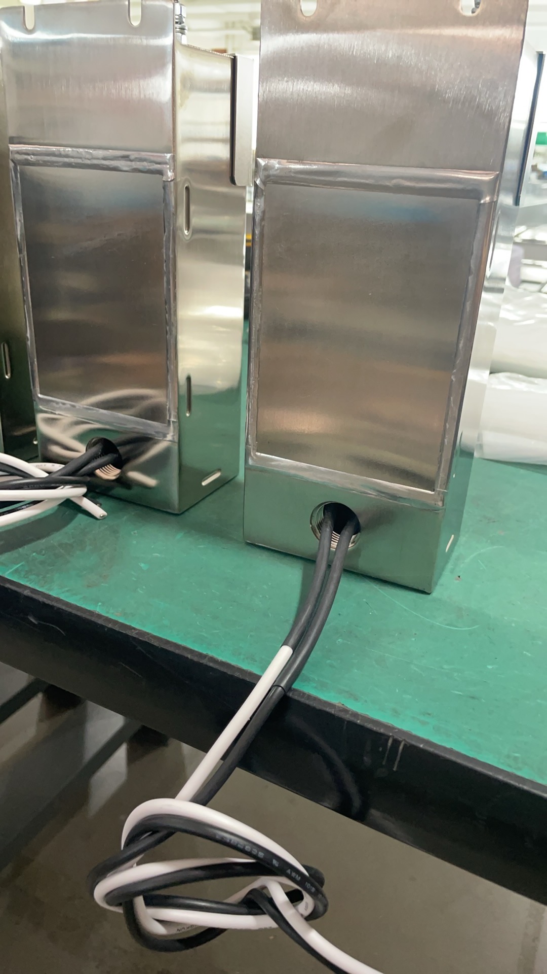
📸 TESTUPS EMI Filters In The Field
Below are real-life photos and videos from recent TESTUPS power-line EMI filter deliveries — the units pictured here are the same models you’ll find in the datasheet tables further down the page.
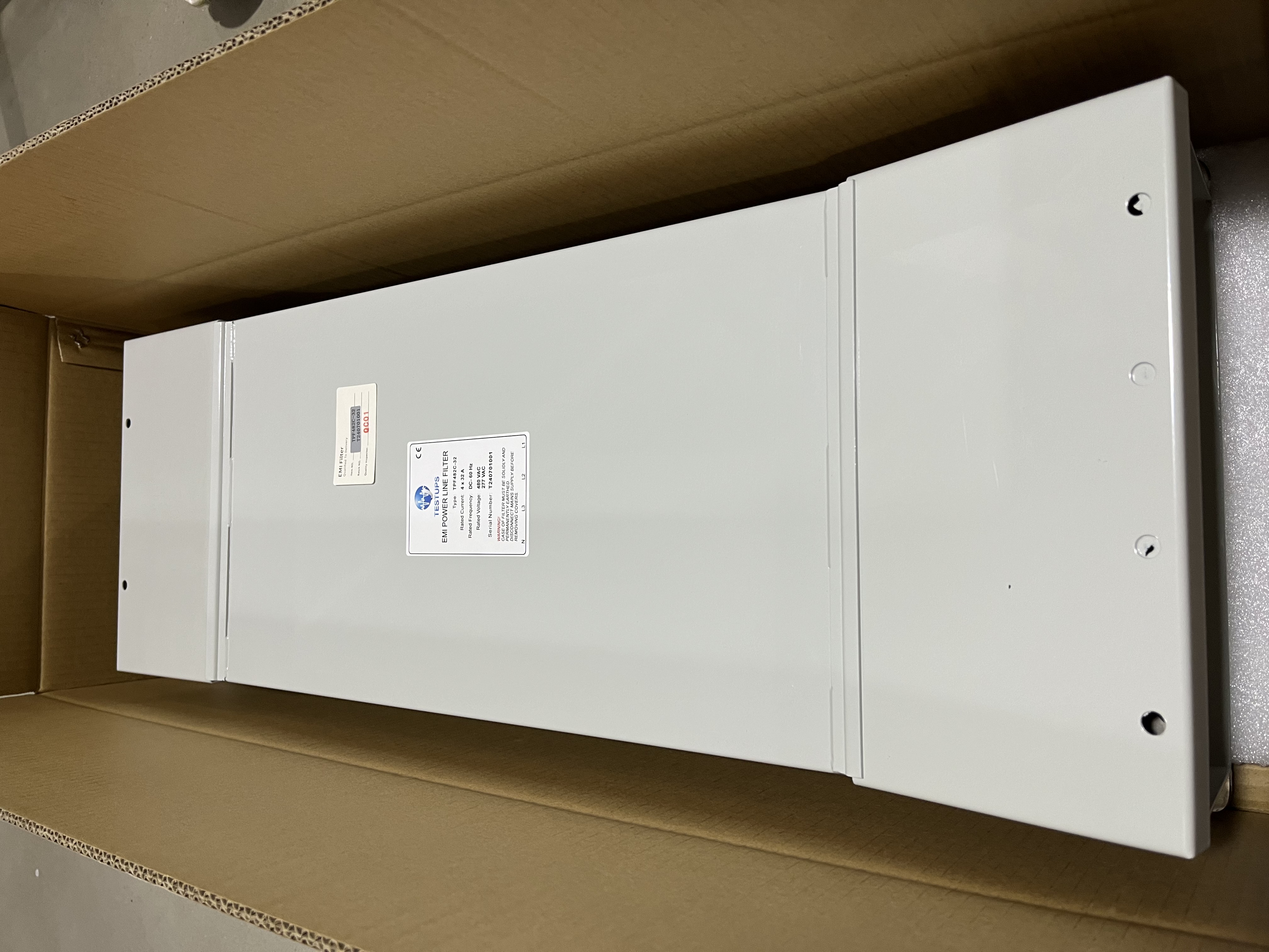
TPF482C-32 — Delivered to Anduril
A 2-line spray-coated EMC-chamber filter (440 VAC / 250 VAC, 32 A) installed on-site.
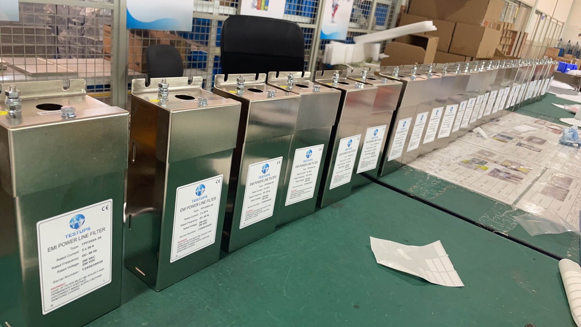
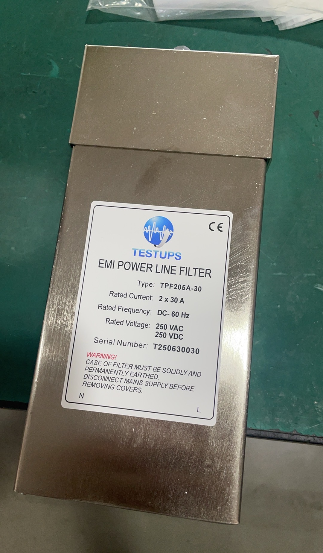
TPF205A-30 — Production Unit
A 2-line nickel-plated single-phase filter (250 VAC / 250 VDC, 30 A) for general shielded-room mains feed-through.
Power Line EMI Filters — Datasheets
The table below lists every TESTUPS power line filter currently in our standard range. Click any PDF ↓ link to download the corresponding datasheet — voltage, current, insertion-loss curves, mechanical drawings, and mounting notes are all included.
| Model | Description | Key Specs | Datasheet |
|---|---|---|---|
| TPF101C-63-400HZ-C1 | 1-line nickel-plated filter (400HZ-C1) | 14 kHz – 40 GHz · 63 A · 277 VAC | PDF ↓ |
| TPF182D-1000-1500VDC | 1-line spray-coated EMC-chamber filter (1500VDC) | 10 kHz – 40 GHz · 1000 A · 1500 VDC | PDF ↓ |
| TPF201A-100 | 2-line nickel-plated filter | 150 kHz – 40 GHz · 100 A · 250 VAC · 500 VDC | PDF ↓ |
| TPF203A-16-ELCB | 2-line nickel-plated filter (ELCB) | 150 kHz – 40 GHz · 16 A | PDF ↓ |
| TPF203A-32-ELCB-250VAC-500VDC | 2-line nickel-plated filter (ELCB-250VAC-500VDC) | 150 kHz – 40 GHz · 32 A | PDF ↓ |
| TPF203C-32-ELCB | 2-line nickel-plated filter (ELCB) | 14 kHz – 40 GHz · 32 A · 277 VAC · 500 VDC | PDF ↓ |
| TPF205A-30 | 2-line nickel-plated filter | 150 kHz – 40 GHz · 30 A · 250 VAC · 250 VDC | PDF ↓ |
| TPF282A-100-1500VDC | 2-line spray-coated EMC-chamber filter (1500VDC) | 150 kHz – 40 GHz · 100 A · 1500 VDC | PDF ↓ |
| TPF282A-16 | 2-line spray-coated EMC-chamber filter | 150 kHz – 40 GHz · 16 A | PDF ↓ |
| TPF282A-200-1000VDC | 2-line spray-coated EMC-chamber filter (1000VDC) | 150 kHz – 40 GHz · 200 A | PDF ↓ |
| TPF282A-32-1500VDC | 2-line spray-coated EMC-chamber filter (1500VDC) | 150 kHz – 40 GHz · 32 A · 1500 VDC | PDF ↓ |
| TPF282A-32-A1 | 2-line spray-coated EMC-chamber filter (A1) | 150 kHz – 40 GHz · 32 A · 250 VAC · 500 VDC | PDF ↓ |
| TPF282A-63-1500VDC | 2-line spray-coated EMC-chamber filter (1500VDC) | 150 kHz – 40 GHz · 63 A · 1500 VDC | PDF ↓ |
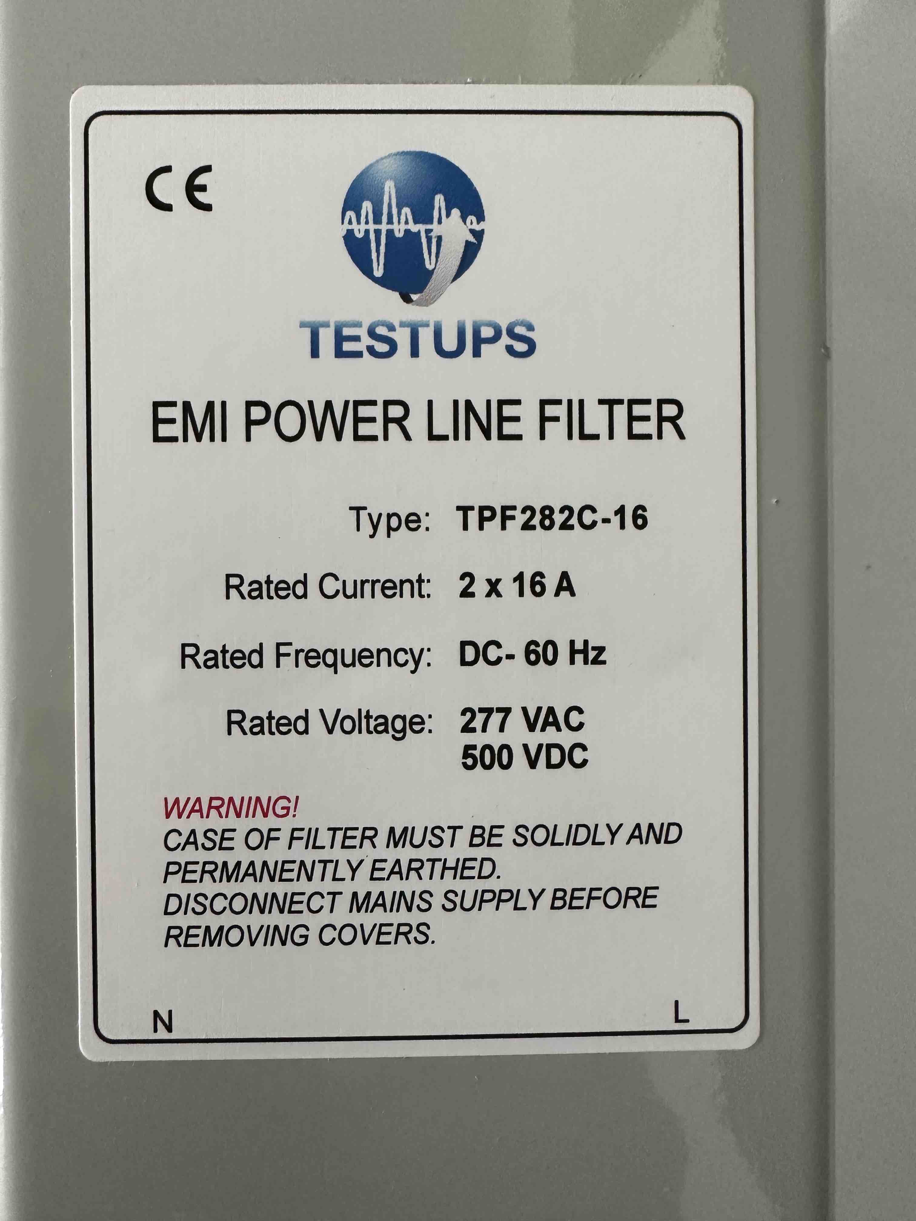
| TPF282C-16 | 2-line spray-coated EMC-chamber filter | 14 kHz – 40 GHz · 16 A · 277 VAC · 500 VDC | PDF ↓ |
| TPF282C-32 | 2-line spray-coated EMC-chamber filter | 14 kHz – 40 GHz · 32 A · 277 VAC · 500 VDC | PDF ↓ |
| TPF282C-32-UL | 2-line spray-coated EMC-chamber filter (UL) | 14 kHz – 40 GHz · 32 A · 250 VAC · 250 VDC | PDF ↓ |
| TPF282C-400 | 2-line spray-coated EMC-chamber filter | 14 kHz – 40 GHz · 400 A | PDF ↓ |
| TPF282C-500-1500VDC | 2-line spray-coated EMC-chamber filter (1500VDC) | 14 kHz – 40 GHz · 500 A | PDF ↓ |
| TPF282C-63 | 2-line spray-coated EMC-chamber filter | 14 kHz – 40 GHz · 63 A | PDF ↓ |
| TPF282D-150-1500VDC | 2-line spray-coated EMC-chamber filter (1500VDC) | 10 kHz – 40 GHz · 150 A · 277 VAC · 1500 VDC | PDF ↓ |
| TPF282D-32 | 2-line spray-coated EMC-chamber filter | 10 kHz – 40 GHz · 32 A | PDF ↓ |
| TPF282D-63-1000VDC | 2-line spray-coated EMC-chamber filter (1000VDC) | 10 kHz – 40 GHz · 63 A | PDF ↓ |
| TPF282D-63 | 2-line spray-coated EMC-chamber filter | 10 kHz – 40 GHz · 63 A | PDF ↓ |
| TPF286C-16 | 2-line spray-coated shielded-room filter | 14 kHz – 40 GHz · 16 A · 250 VAC · 500 VDC | PDF ↓ |
| TPF382A-32 | 3-line spray-coated EMC-chamber filter | 150 kHz – 40 GHz · 32 A · 440 VAC · 250 VAC | PDF ↓ |
| TPF403A-32-ELCB | 4-line nickel-plated filter (ELCB) | 150 kHz – 40 GHz · 32 A | PDF ↓ |
| TPF403C-32-ELCB | 4-line nickel-plated filter (ELCB) | 14 kHz – 40 GHz · 32 A | PDF ↓ |
| TPF462C-1600-690VAC | 4-line brushed EMC-chamber filter (690VAC) | 14 kHz – 40 GHz · 1600 A · 690 VAC | PDF ↓ |
| TPF462C-500-690VAC-1000VDC-P | 4-line brushed EMC-chamber filter (690VAC-1000VDC-P) | 14 kHz – 40 GHz · 500 A · 690 VAC · 1000 VDC | PDF ↓ |
| TPF482A-16-32 | 4-line spray-coated EMC-chamber filter (32) | 150 kHz – 40 GHz · 16 A | PDF ↓ |
| TPF482A-200 | 4-line spray-coated EMC-chamber filter | 150 kHz – 40 GHz · 200 A | PDF ↓ |
| TPF482A-32 | 4-line spray-coated EMC-chamber filter | 150 kHz – 40 GHz · 32 A · 440 VAC · 250 VAC | PDF ↓ |
| TPF482C-100 | 4-line spray-coated EMC-chamber filter | 14 kHz – 40 GHz · 100 A · 480 VAC · 277 VAC | PDF ↓ |
| TPF482C-150-690VAC | 4-line spray-coated EMC-chamber filter (690VAC) | 14 kHz – 40 GHz · 150 A | PDF ↓ |
| TPF482C-250-690VAC-1500VDC | 4-line spray-coated EMC-chamber filter (690VAC-1500VDC) | 14 kHz – 40 GHz · 250 A | PDF ↓ |
| TPF482C-32 | 4-line spray-coated EMC-chamber filter | 14 kHz – 40 GHz · 32 A · 440 VAC · 250 VAC | PDF ↓ |
| TPF482C-63 | 4-line spray-coated EMC-chamber filter | 14 kHz – 40 GHz · 63 A · 440 VAC · 250 VAC | PDF ↓ |
| TPF482D-16 | 4-line spray-coated EMC-chamber filter | 10 kHz – 40 GHz · 16 A · 440 VAC · 250 VAC | PDF ↓ |
| TPF482D-32 | 4-line spray-coated EMC-chamber filter | 10 kHz – 40 GHz · 32 A · 440 VAC · 250 VAC | PDF ↓ |
| TPF486C-100-A3 | 4-line spray-coated shielded-room filter (A3) | 14 kHz – 40 GHz · 100 A · 480 VAC · 277 VAC | PDF ↓ |
| TPF486C-200-440VAC | 4-line spray-coated shielded-room filter (440VAC) | 14 kHz – 40 GHz · 200 A | PDF ↓ |
| TPF486C-63 | 4-line spray-coated shielded-room filter | 14 kHz – 40 GHz · 63 A | PDF ↓ |
| TPF486C-63-UL | 4-line spray-coated shielded-room filter (UL) | 14 kHz – 40 GHz · 63 A | PDF ↓ |
| TPF486C-630-A3 | 4-line spray-coated shielded-room filter (A3) | 14 kHz – 40 GHz · 630 A · 480 VAC · 277 VAC | PDF ↓ |
Signal Line EMI Filters — Datasheets
Signal line filters protect data and control lines — USB, LAN, RS-232/485, and similar — that run separately from the main power conductors. They share the same shielding-effectiveness goal as power-line filters but are tuned for the lower currents and higher data rates of signal cabling.
| Model | Description | Key Specs | Datasheet |
|---|---|---|---|
| TSF210-1-A2 | Single-line signal-line EMI filter | 250 VDC | PDF ↓ |
| TSF210-1-A5 | Single-line signal-line EMI filter | 250 VAC / 250 VDC | PDF ↓ |
| TSF203-1-A2 | Single-line signal-line EMI filter | 250 VDC | PDF ↓ |
| TSF403-1 | Single-line signal-line EMI filter | 250 VDC · 1 A | PDF ↓ |
| TSF-LAN1000-04P | 4-port gigabit LAN signal-line filter | 100-250 VAC | PDF ↓ |
| TSF-LAN-USB | Combined LAN + USB 2.0 signal filter | USB 2.0 | PDF ↓ |
| TFC-USB3L | USB 3.0 SuperSpeed signal-line filter | USB 3.0 | PDF ↓ |
How TESTUPS Can Help
TESTUPS supplies the full TPFXY6 and TPFXY2 ranges for both shielded-room and EMC-chamber integration, in custom line counts, surface finishes, and current ratings from a few amperes up to several hundred amperes. Our engineering team will help you match the right model to your facility’s frequency coverage, current rating, and mounting constraints — and we ship globally with full validation reports. For related information, see our guides on conducted emissions testing and EMC test chamber design.

Need Expert EMC Assistance?
TESTUPS provides complete EMC solutions — from test equipment and anechoic chambers to certification services. Contact our team for tailored support.