CISPR 25 Anechoic Chamber — Requirements & Specifications
Detailed guide to anechoic chamber requirements for CISPR 25 automotive emissions testing, covering chamber dimensions, shielding, RF absorber specifications, and the ALSE measurement method.
Introduction
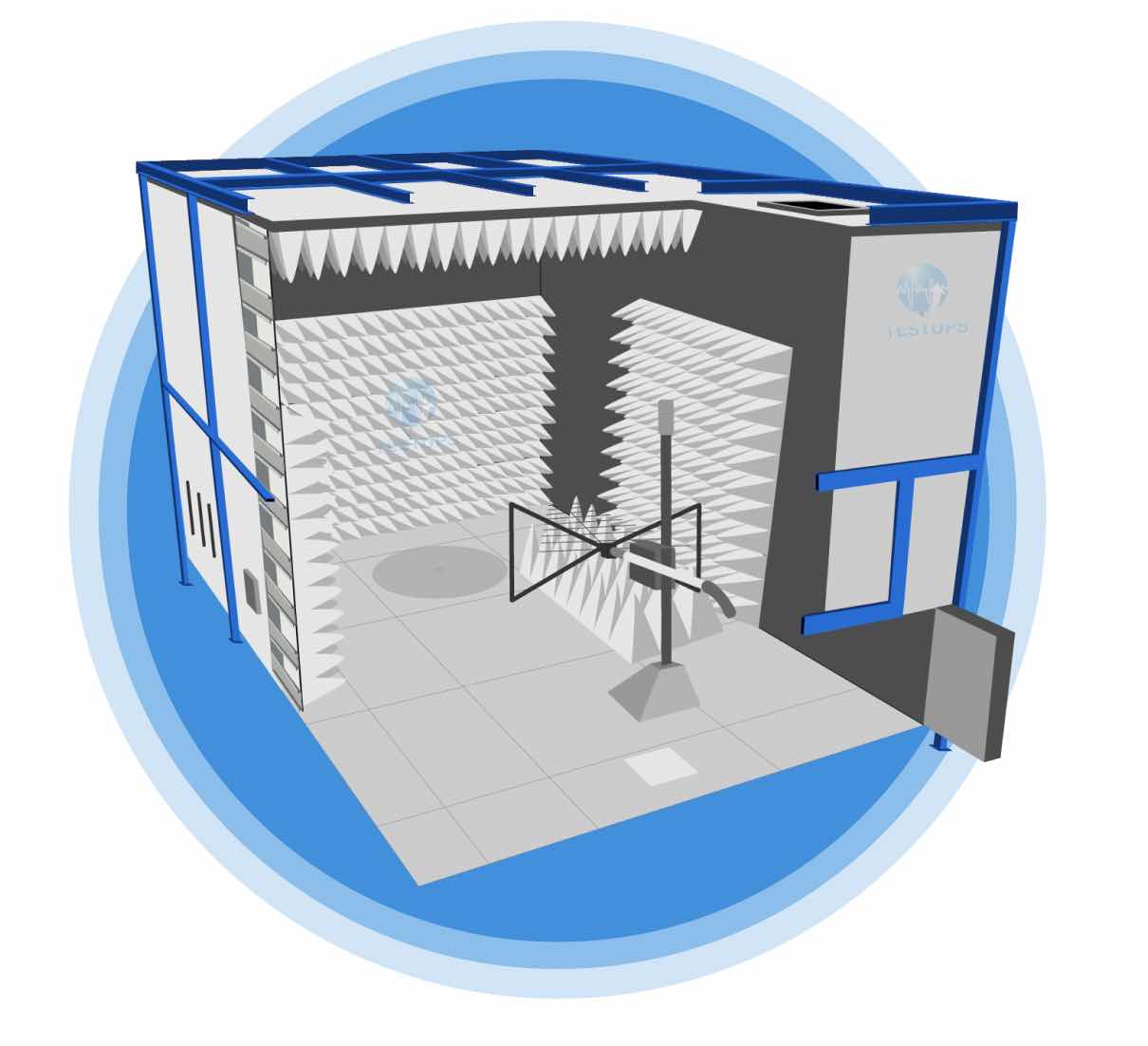
Accurate and reproducible CISPR 25 measurements require a controlled electromagnetic environment that eliminates external interference and minimizes internal reflections. The Absorber Lined Shielded Enclosure (ALSE) method is the standard test environment specified in CISPR 25 for radiated emission measurements of automotive components. An ALSE is essentially an anechoic chamber: a shielded room lined with radio frequency (RF) absorbing material that suppresses reflections from the chamber walls, ceiling, and (in some configurations) the floor.
Designing and constructing a CISPR 25 anechoic chamber requires careful attention to shielding effectiveness, absorber performance, chamber geometry, ground plane configuration, and background noise levels. This article covers the key technical requirements that a CISPR 25 test chamber must satisfy.
Shielding Effectiveness
The outer structure of a CISPR 25 anechoic chamber is a shielded enclosure designed to attenuate external electromagnetic signals and prevent them from interfering with the sensitive emission measurements being conducted inside. The shielding must provide sufficient attenuation across the entire CISPR 25 measurement frequency range of 150 kHz to 2500 MHz.
Typical shielding effectiveness requirements for a CISPR 25 chamber are:
| Frequency Range | Minimum Shielding Effectiveness |
|---|---|
| 150 kHz - 30 MHz | 80 dB (magnetic and electric field) |
| 30 MHz - 1000 MHz | 80 - 100 dB (plane wave) |
| 1000 MHz - 2500 MHz | 80 - 100 dB (plane wave) |
The shielding is typically achieved using welded steel or modular galvanized steel panel construction. All seams, joints, door gaskets, ventilation penetrations, and cable entry panels must maintain the required shielding effectiveness. Shielded enclosure doors use finger stock or knife-edge gasket systems to maintain electromagnetic integrity during normal operation.
Power line filters, signal line filters, and fiber optic feedthroughs are used for all electrical and data connections passing through the shielded enclosure walls. These filters must provide adequate attenuation at all frequencies of interest.
RF Absorber Requirements
RF absorbers are the defining feature that distinguishes an anechoic chamber from a simple shielded room. The absorbers are mounted on the interior surfaces of the chamber to suppress reflections of electromagnetic energy from the chamber walls and ceiling. For CISPR 25 applications, the absorber selection and placement must be appropriate for the measurement frequency range.
Absorber Types
Two primary types of RF absorbers are used in CISPR 25 chambers:
-
Ferrite tile absorbers: Effective at lower frequencies, typically from 30 MHz to 1000 MHz. Ferrite tiles are thin, flat panels made from sintered ferrite material. They provide good absorption at lower frequencies without consuming significant chamber volume. Ferrite absorbers are essential for achieving acceptable performance below 200 MHz.
-
Pyramidal foam absorbers: Effective at higher frequencies, typically from 200 MHz and above. These are wedge-shaped or pyramidal foam structures loaded with carbon. The pyramid geometry provides a gradual impedance transition from free space to the absorber material, resulting in low reflectivity. Pyramid height determines the lowest effective frequency: taller pyramids absorb lower frequencies.
Most CISPR 25 chambers use a hybrid absorber configuration combining ferrite tiles on the chamber walls with pyramidal foam absorbers placed over the ferrite tiles. This combination provides broadband absorption from 30 MHz to well above 2500 MHz.
Absorber Placement
For CISPR 25 radiated emission measurements using the ALSE method, absorbers are placed on:
- All four walls: Full coverage from the floor line to the ceiling.
- Ceiling: Full coverage across the entire ceiling area.
- Floor: The floor is not lined with absorbers. Instead, a metallic ground plane is used on the floor, as CISPR 25 specifies a ground-plane-based measurement method.
This configuration creates a “semi-anechoic” environment: the walls and ceiling absorb reflections, while the ground plane provides a controlled reflective surface that is part of the measurement setup.
Chamber Dimensions
The internal dimensions of a CISPR 25 anechoic chamber must be large enough to accommodate the device under test (DUT), the wiring harness, the measurement antenna, and sufficient separation from the absorber-lined walls to avoid near-field coupling effects. While CISPR 25 does not mandate a specific chamber size, the following practical considerations determine minimum dimensions:
Minimum Dimension Guidelines
| Parameter | Typical Requirement |
|---|---|
| DUT-to-antenna distance | 1 m (as specified in CISPR 25) |
| Harness length | 1500 mm typical |
| Clearance from DUT to absorber walls | At least 1 m recommended |
| Clearance from antenna to absorber walls | At least 1 m recommended |
| Ground plane extent beyond DUT/harness | At least 200 mm on all sides |
A common chamber size for CISPR 25 testing is approximately 5 m (L) x 3 m (W) x 3 m (H) internal usable dimensions (before absorber installation). Larger chambers provide better performance at lower frequencies and more flexibility in test setup configurations. Smaller chambers may be acceptable for testing small ESAs with short harnesses, provided that the validation measurements confirm acceptable performance.
Chamber Validation
The CISPR 25 chamber must be validated to confirm that its electromagnetic performance is adequate for the intended measurements. The key validation criterion is the background noise level: the ambient electromagnetic noise inside the chamber (with no DUT operating) must be at least 6 dB below the lowest applicable emission limit across the entire measurement frequency range.
This validation is performed by measuring the ambient noise spectrum inside the chamber using the same measurement equipment and antenna configurations that will be used for DUT testing.
Ground Plane
The ground plane is a metallic surface on the chamber floor that serves as the reference conductor for the CISPR 25 test setup. It must be electrically conductive and provide a low-impedance surface across the full frequency range.
Ground plane requirements include:
- Material: Copper, aluminum, or galvanized steel sheet with a minimum thickness of 0.5 mm.
- Surface condition: Clean, free of corrosion, and electrically continuous. Joints between ground plane sections must be bonded using conductive tape or overlapping seams.
- Size: Must extend at least 200 mm beyond the edges of the DUT and wiring harness on all sides.
- Connection to shielded enclosure: The ground plane must be bonded to the shielded enclosure walls to establish a common ground reference.
Antenna Positioning
CISPR 25 specifies precise antenna positioning requirements for radiated emission measurements:
- Measurement distance: 1 meter from the nearest point of the wiring harness to the antenna reference point.
- Antenna height: The antenna center is positioned at the same height as the wiring harness (typically 50 mm above the ground plane for a monopole rod, or at harness height for other antenna types).
- Antenna polarization: Both vertical and horizontal polarizations are measured (except for the monopole rod antenna, which is inherently vertically polarized).
- Antenna scanning: The antenna may be moved along the length of the harness to identify the position of maximum emission.
Different antenna types are used for different frequency bands, as described in the CISPR 25 test setup requirements.
Background Noise Requirements
The ambient electromagnetic noise inside the CISPR 25 chamber must be sufficiently low to allow valid emission measurements. The standard requires that background noise levels be at least 6 dB below the applicable limit at all frequencies. In practice, many test laboratories aim for background noise levels that are 10 dB or more below the limit to provide additional measurement margin.
Achieving low background noise requires:
- High shielding effectiveness of the enclosure.
- Proper filtering of all power and signal lines entering the chamber.
- Isolation of noisy support equipment (power supplies, load simulators, control computers) outside the shielded enclosure.
- Use of fiber optic connections for data transfer between the DUT and external equipment where possible.
How TESTUPS Can Help
TESTUPS designs, builds, and validates CISPR 25 anechoic chambers tailored to automotive component testing requirements. Our chamber solutions feature high-performance shielded enclosures, hybrid ferrite and pyramidal absorber systems, precision ground planes, and validated background noise performance. We also supply complete turnkey CISPR 25 test systems including EMI receivers, LISNs, calibrated antennas, and automated test software. Whether you need a new chamber installation or an upgrade to an existing facility, TESTUPS provides engineering support from design through commissioning and accreditation.
Contact TESTUPS to discuss your CISPR 25 anechoic chamber project.
Need Expert EMC Assistance?
TESTUPS provides complete EMC solutions — from test equipment and anechoic chambers to certification services. Contact our team for tailored support.