ISO 11452-4 — Bulk Current Injection (BCI) Test Requirements
Complete guide to ISO 11452-4 bulk current injection (BCI) test requirements for automotive EMC immunity testing, including frequency ranges, test levels, probe specifications, calibration, and setup procedures.
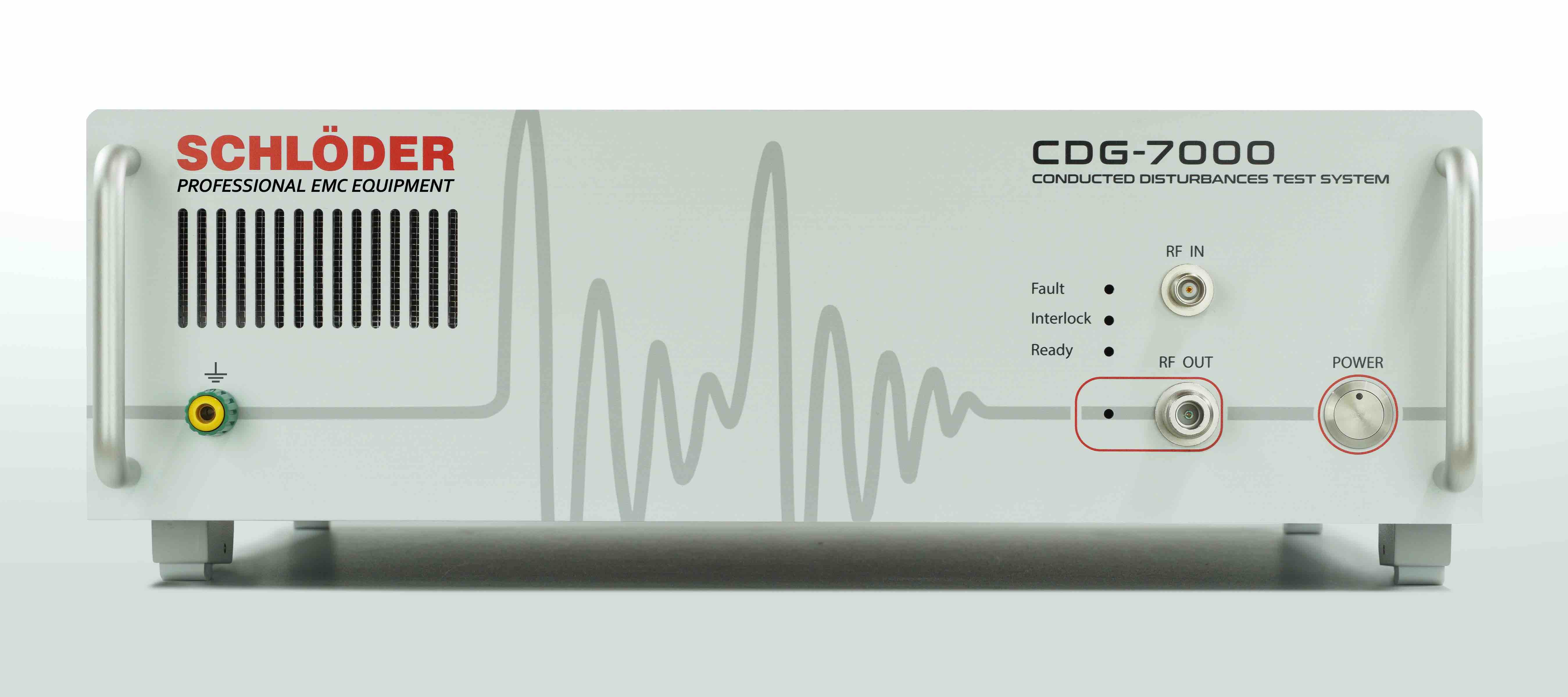
Overview of ISO 11452-4
ISO 11452-4 specifies the bulk current injection (BCI) method for testing the electromagnetic immunity of electronic components and modules installed in road vehicles. BCI is one of the most widely used immunity test methods in automotive EMC because it provides an efficient way to inject RF energy into wiring harnesses, simulating the electromagnetic fields that cables would pick up in real-world driving conditions.
The BCI method works by clamping an injection probe (a current transformer) around the wiring harness of the device under test (DUT) and driving RF current into the cables over a defined frequency range. This couples energy into the DUT in a manner that replicates the effect of radiated RF fields impinging on the vehicle wiring.
BCI testing is referenced extensively in OEM EMC specifications including Ford FMC 1278, Volkswagen TL 81000, BMW GS 95024, and many others, as well as in the harmonized regulation ECE R10.
Frequency Range
ISO 11452-4 defines the standard BCI test frequency range as 1 MHz to 400 MHz. This range covers the frequencies where cable-coupled immunity is most relevant for automotive electronic systems. Some OEM specifications extend the upper frequency to 1 GHz, but the standard range remains 1 MHz to 400 MHz.
The frequency sweep is typically performed in logarithmic steps, with a minimum step size of 1% of the current test frequency (or finer, depending on the product specification). Dwell time at each frequency is typically 2 seconds or as specified by the applicable OEM standard.
Test Levels
ISO 11452-4 defines test severity levels based on the injected current (in milliamperes, expressed in dBuA):
| Severity Level | Injected Current (mA rms) | Level (dBuA) |
|---|---|---|
| I | 1 | 60 |
| II | 3.16 | 70 |
| III | 10 | 80 |
| IV | 31.6 | 90 |
| V | 100 | 100 |
The required test level is specified by the vehicle manufacturer or the applicable regulation. Most OEMs require levels between 60 mA (Level III) and 200 mA or higher, depending on the component location and function within the vehicle.
Injection Probe Requirements
The injection probe is a critical element of the BCI test setup. It is essentially a current transformer that clamps around the wire harness bundle and couples RF energy into the cables. Key requirements include:
- Frequency range: Must cover the full test frequency range (typically 1 MHz to 400 MHz or beyond).
- Insertion impedance: Should be low enough to avoid significantly altering the circuit impedance of the harness.
- Power handling: Must be rated for the maximum forward power required to achieve the specified injection current.
- Clamping mechanism: Must allow easy, repeatable placement around the harness without damaging cables.
Common injection probes are manufactured by companies such as Fischer Custom Communications (FCC), Teseq, and ETS-Lindgren. The probe’s transfer impedance characteristics must be known and accounted for during the calibration and substitution process.
Monitoring Probe
In addition to the injection probe, a monitoring probe (also a current transformer) is used to measure the actual current flowing in the harness. The monitoring probe is placed on the harness at a defined distance from the injection probe (typically 50 mm from the DUT connector). It provides real-time feedback on the injected current level, which is essential for closed-loop level control and for the substitution method calibration.
Key monitoring probe requirements:
- Calibrated transfer impedance across the full frequency range
- Low insertion impedance to minimize harness disturbance
- Adequate bandwidth and dynamic range for the test levels used
Calibration: The Substitution Method
ISO 11452-4 employs the substitution method for calibrating the BCI test setup. This method accounts for the combined effects of the injection probe, the amplifier, and the signal path, ensuring that the correct current level is injected into the harness regardless of frequency-dependent variations.
Calibration Procedure
- Prepare a calibration fixture — A 50-ohm coaxial calibration jig replaces the DUT harness. The injection probe is clamped around the jig in the same position as it will be during the actual test.
- Set the monitoring probe at the defined position on the calibration jig.
- Sweep the frequency range while adjusting the forward power at each frequency step to achieve the required current level as measured by the monitoring probe.
- Record the forward power required at each frequency point. This data becomes the power reference table for the actual test.
During the actual DUT test, the system applies the recorded forward power levels from the calibration. The monitoring probe is used to verify that the injected current is within acceptable tolerances.
DUT Setup and Harness Configuration
Proper DUT setup is critical for repeatable BCI test results. ISO 11452-4 specifies:
- Test bench: The DUT is mounted on a ground plane (metallic bench) at a height of 50 mm above the ground plane, supported by non-conductive spacers.
- Harness length: The total harness length is typically 1700 mm (or as specified by the OEM), routed along the ground plane at a height of 50 mm.
- Harness routing: The harness runs in a straight line from the DUT to the load simulator (artificial network or vehicle simulation network).
- Load simulator: An appropriate load simulator or wire harness simulation unit terminates the harness, representing the vehicle electrical environment.
- Injection probe position: The injection probe is placed at a defined distance from the DUT connector (typically 150 mm from the DUT, but positions may vary by OEM specification). Some specifications require testing at multiple probe positions along the harness.
- Monitoring probe position: Placed between the injection probe and the DUT connector, typically 50 mm from the DUT.
- Power supply: The DUT is powered through appropriate power supply networks with defined impedance characteristics. LISN (Line Impedance Stabilization Network) or AN (Artificial Network) may be required.
- Grounding: The DUT ground connection must replicate the actual vehicle mounting configuration.
Test Procedure Summary
- Install the DUT on the test bench with the specified harness and load simulator.
- Verify DUT normal operation and establish baseline performance.
- Position the injection and monitoring probes at the specified locations.
- Perform the substitution calibration to establish the power reference table.
- Apply the calibrated power levels across the frequency range while the DUT is operating.
- Monitor DUT performance throughout the test, recording any anomalies, malfunctions, or deviations from normal operation.
- Classify DUT performance according to the applicable pass/fail criteria (e.g., Class A through Class E, depending on the OEM specification).
How TESTUPS Can Help
TESTUPS provides complete BCI testing services in accordance with ISO 11452-4 and all major automotive OEM specifications. Our test facilities are equipped with calibrated injection and monitoring probes, high-power RF amplifiers, and automated test systems capable of performing substitution-method BCI testing across the full frequency range. Whether you need pre-compliance BCI screening during development or full qualification testing for OEM approval, TESTUPS delivers accurate, efficient results. Contact us to discuss your automotive immunity testing requirements or to explore our automotive EMC test systems.
Need Expert EMC Assistance?
TESTUPS provides complete EMC solutions — from test equipment and anechoic chambers to certification services. Contact our team for tailored support.