DIY RF Anechoic Chamber — Guide to Building Your Own EMC Chamber
A practical guide to building a DIY RF anechoic chamber for pre-compliance EMC testing, covering basic components, common construction approaches, limitations compared to professional chambers, and when a professional facility is necessary.
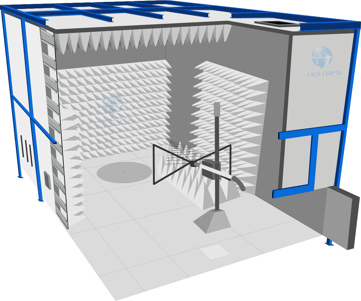
Introduction: Can You Build Your Own EMC Chamber?
Building a DIY RF anechoic chamber is a question that many hardware engineers, startups, and small electronics companies consider when facing the cost of professional EMC testing. A well-constructed DIY chamber can be a valuable tool for pre-compliance testing, design debugging, and early-stage EMC evaluation. However, it is essential to understand the practical limitations of a DIY approach compared to a professional, validated EMC test facility.
This guide covers the fundamental components, construction approaches, typical performance achievable with a DIY build, and the important distinction between pre-compliance screening and formal compliance testing.
Basic Components of an RF Anechoic Chamber
An RF anechoic chamber consists of several core components that work together to create a controlled electromagnetic environment:
1. Shielded Enclosure
The shielded enclosure forms the outer boundary of the chamber and prevents external electromagnetic signals from entering the measurement space (and prevents internal signals from leaking out). Shielding effectiveness is the most critical parameter.
DIY approaches:
- Welded steel enclosure — Steel sheets (1-2 mm thick) welded at all seams provide good shielding (typically 60-80 dB at frequencies up to 1 GHz). This requires welding skills and workshop space.
- Copper or aluminum-lined room — A wooden or metal frame lined with copper or aluminum sheet, with all joints overlapped and soldered or taped with conductive EMI tape. Achievable shielding is lower (30-50 dB) and highly dependent on joint quality.
- Modular shielded panels — Pre-fabricated shielded panels can be purchased and assembled into an enclosure. This offers better shielding consistency than DIY sheet metal construction but at higher cost.
Key considerations:
- All joints, seams, and penetrations (cables, ventilation, door) must maintain RF continuity. Even small gaps drastically reduce shielding effectiveness.
- The door is typically the weakest point. A professional RF door with finger-stock gaskets or knife-edge contacts is strongly recommended, even for DIY builds.
- Cable penetrations must use bulkhead connectors or filtered feedthroughs.
2. RF Absorbers
RF absorbers line the interior of the shielded enclosure to reduce reflections and create a pseudo-free-space environment. For a DIY chamber, the most practical options are:
- Carbon-loaded pyramid foam — Available commercially in various heights. Larger pyramids provide better low-frequency performance but consume interior space. A minimum pyramid height of 300-600 mm is typical for usable performance above 200-300 MHz.
- Ferrite tiles — Effective at lower frequencies (30-600 MHz) but expensive and heavy. Ferrite is generally impractical for a budget DIY build unless sourced as surplus.
- Hybrid absorbers — Offer broadband coverage but are the most expensive option.
For a cost-effective DIY build, pyramid foam absorbers covering the walls and ceiling (and floor if building a fully anechoic chamber) provide the best balance of cost and performance.
3. RF Door and Access
The chamber door must maintain shielding integrity when closed. Options include:
- Commercial RF doors — The best option for shielding performance (60-100 dB), but expensive. Available from specialized manufacturers.
- DIY sliding contact door — A steel door with copper finger stock or conductive gasket material around the frame. Performance depends heavily on construction quality.
- Knife-edge contact doors — Provide excellent shielding with a simple mechanical design, but require precision fabrication.
4. Ventilation and Filtered Penetrations
Electronic equipment inside the chamber generates heat, so ventilation is necessary. However, ventilation openings compromise shielding unless they are filtered:
- Honeycomb waveguide ventilation panels — Arrays of small hexagonal or circular tubes act as waveguides below cutoff, passing air while blocking RF energy. These can be purchased commercially or fabricated from aluminum honeycomb core material.
- Filtered power and signal feedthroughs — All cables entering the chamber must pass through filtered bulkhead connectors or feedthrough panels to prevent conducted RF leakage.
Common DIY Construction Approaches
Small Desktop Chamber
Suitable for testing small PCBs, modules, and IoT devices. Typically built from steel or aluminum sheet with internal foam absorbers.
- Size: Approximately 60 cm x 60 cm x 60 cm to 100 cm x 100 cm x 100 cm
- Shielding: 40-60 dB achievable with careful construction
- Absorber: Small pyramid foam (100-300 mm)
- Usable frequency: 500 MHz to 6 GHz (limited low-frequency performance)
- Cost: A few hundred to a few thousand dollars
Walk-In Room
A room-sized chamber suitable for testing larger equipment, automotive components, or performing antenna measurements.
- Size: 2 m x 2 m x 2 m or larger
- Shielding: 60-80 dB with welded steel construction and a proper RF door
- Absorber: Pyramid foam 300-1000 mm on walls and ceiling; metallic floor for semi-anechoic configuration
- Usable frequency: 200 MHz to 18 GHz (with sufficiently large absorbers)
- Cost: Several thousand to tens of thousands of dollars
Limitations of DIY Chambers vs. Professional Facilities
While a DIY chamber can serve well for pre-compliance and design iteration, it is important to understand its limitations:
| Aspect | DIY Chamber | Professional Chamber |
|---|---|---|
| Shielding effectiveness | 30-80 dB (variable, depends on construction) | 80-120 dB (consistent, validated) |
| Frequency range | Limited at low frequencies (<200 MHz) | Full range (30 MHz to 40 GHz+) |
| Site validation | Not validated to CISPR 16-1-4 or ANSI C63.4 | NSA validated, traceable calibration |
| Measurement uncertainty | Unknown or large | Quantified and documented |
| Accreditation | Not applicable | ISO/IEC 17025 accredited |
| Regulatory acceptance | Not accepted for compliance testing | Accepted by regulatory bodies worldwide |
| Absorber performance | Adequate for screening | Optimized for full-band performance |
| Cost | Hundreds to tens of thousands of dollars | Hundreds of thousands to millions of dollars |
When Is a DIY Chamber Sufficient?
A DIY RF anechoic chamber is well suited for:
- Pre-compliance screening — Identifying major EMC issues before sending the product to an accredited lab, reducing the risk of expensive test failures.
- Design debugging — Comparing design iterations, evaluating shielding effectiveness of enclosures, and testing filtering performance.
- Component-level evaluation — Measuring relative emission levels of PCBs, cables, and connectors during development.
- Education and training — Learning EMC measurement techniques and building engineering intuition.
- RF development — Antenna pattern measurements, RF device characterization at microwave frequencies.
When Do You Need a Professional Chamber?
Professional, accredited EMC testing is required for:
- Regulatory compliance — CE marking, FCC certification, E-mark type approval, medical device certification (IEC 60601-1-2), and all other formal certifications require testing in an accredited facility.
- OEM qualification — Automotive OEMs such as Ford (FMC 1278) require testing at accredited laboratories.
- Immunity testing — Formal immunity testing (ESD per IEC 61000-4-2, BCI per ISO 11452-4, radiated immunity) requires calibrated test systems and validated chamber environments.
- Emissions measurements below 200 MHz — The low-frequency range is very difficult to address in a DIY chamber without large ferrite or hybrid absorbers.
- Legal and liability purposes — Accredited test reports carry legal weight; DIY measurements do not.
TESTUPS as a Professional Alternative
While building a DIY chamber can support your engineering development process, TESTUPS provides the professional EMC testing infrastructure needed for formal compliance and certification. TESTUPS offers:
- Fully validated and accredited EMC test chambers for emission and immunity testing
- Complete test services for automotive, medical, industrial, and consumer electronics standards
- RF absorbers and chamber components for customers building or upgrading their own facilities
- Pre-compliance testing support to bridge the gap between DIY screening and formal compliance
Whether you are building a DIY chamber for your lab or need accredited compliance testing, TESTUPS is your partner for EMC. Contact our team to discuss your testing requirements or to source RF absorbers and shielding materials for your DIY project.
Need Expert EMC Assistance?
TESTUPS provides complete EMC solutions — from test equipment and anechoic chambers to certification services. Contact our team for tailored support.